Table of Contents >> Show >> Hide
- Why the Zynq-7000 Still Earns Bench Space
- Start With Requirements, Not With a Shopping Cart
- Power: The Unsexy Foundation That Keeps the Magic Smoke Employed
- DDR: Welcome to the Land of Millimeters and Mild Panic
- Clocks and Reset: Two Small Nets, One Big Mood
- Boot and Debug: Make It Talk Before You Make It Think
- USB, Ethernet, and HDMI: Your Peripherals Have Opinions
- PCB Layout: Escaping the BGA Without Losing Your Mind
- Bring-Up: A Calm, Repeatable Plan Beats Heroics
- Common Pitfalls (A.K.A. Things That Have Ruined Many Saturdays)
- Final Thoughts: The Point Isn’t to “Compete” With Commercial Dev Boards
- Field Notes: What “From the Ground Up” Feels Like in Practice (500+ Words)
There are two kinds of people in the world: those who buy a dev board and get on with their lives… and those who look at a
484-ball BGA and think, “I could totally make that work.” If you’re reading this, congratulationsyou’re in the second group.
You are also one slightly crooked stencil pull away from learning more about power rails than you ever wanted to know.
Hackaday recently highlighted a deep, practical build series where the creator designs a custom Zynq-7000 development board from scratchcovering
the power system, DDR memory, USB, HDMI, and eventually booting PetaLinux. That’s the “from the ground up” energy we’re channeling here:
not a glossy marketing overview, but a real-world, step-by-step blueprint for turning a Zynq-7000 chip into a working, debuggable,
Linux-booting board you can actually develop on.
Why the Zynq-7000 Still Earns Bench Space
The Zynq-7000 family is a classic “best of both worlds” part: a dual-core ARM Cortex-A9 processing system (PS) tightly coupled to
7-series programmable logic (PL). In plain English, you get a real CPU that can run bare-metal code or Linux, plus FPGA fabric that can
accelerate the parts of your project that don’t enjoy waiting around (video pipelines, custom I/O, high-speed data shaping, weird protocols,
etc.).
It’s also an ecosystem win. The Zynq-7000 has years of documentation, reference designs, and proven board layouts behind it. That matters when you’re
building hardware that includes DDR routing and high-speed interfacesbecause “I’ll just wing it” is how you end up winging your board into the trash.
Start With Requirements, Not With a Shopping Cart
Before you place a single symbol in your schematic tool, write down what “done” looks like. Not what’s coolwhat’s required.
This will keep your design from turning into a “dev board plus a dev board plus a dev board” pile of features that never quite works.
Key decisions to lock early
- Which Zynq? Common choices include the Z-7010/Z-7020 class parts depending on logic resources and peripherals.
- Package and pitch: Your PCB stackup, breakout strategy, and layer count depend heavily on this.
- Memory: DDR3/DDR3L/LPDDR2, bus width (16-bit vs 32-bit), size, and placement.
- Boot media: QSPI flash, microSD, JTAG boot for development, or a “belt and suspenders” combo.
- I/O philosophy: How much goes through MIO (PS pins) vs PL I/O banks?
- Peripherals: USB (needs an external ULPI PHY), Ethernet (needs an external PHY + magnetics), display (HDMI via PL), audio, etc.
- Physical constraints: Board size, connectors, mounting holes, thermal plan.
A practical approach is to keep Rev A intentionally “boring”: power, clocks, DDR, boot, JTAG, UART, and one or two must-have peripherals.
Every extra interface is an extra way to fail your bring-up schedule.
Power: The Unsexy Foundation That Keeps the Magic Smoke Employed
Zynq boards don’t fail because your HDL is wrong (okay, they also fail for that). They fail because power is hard:
multiple rails, strict decoupling, fast transient loads, and layout rules that punish “close enough.”
Your first job is to build a clean, documented power tree. Most Zynq-7000 designs end up with rails for core, auxiliary, and I/O domains,
plus separate requirements for DDR memory (and sometimes a termination rail depending on topology and memory choice).
The Zynq PCB design guidance goes deep on power distribution, capacitor selection, placement, and measurement strategiesuse it like your
board’s constitution, not a casual suggestion.
A realistic power strategy
- Choose your input: 12V barrel, 5V USB-C, or something elsethen decide how you generate intermediate rails (like 5V).
- Generate “board rails” first: 5V and 3.3V often feed other regulators, PHYs, and connectors.
- Generate Zynq rails with sequencing in mind: Some rails must ramp within certain relationships; verify requirements for your device.
- Plan measurement points: Add labeled test pads for each critical rail so you can probe without performing PCB surgery.
- Budget current honestly: CPU + FPGA + DDR + peripherals add up fast, especially during transients.
Also: don’t treat decoupling like a vibes-based activity. High-frequency caps must be physically close to the relevant power pins with tight return paths.
Bulk caps belong where they can stabilize slower droops without adding inductance nightmares. Your layout is the circuit.
DDR: Welcome to the Land of Millimeters and Mild Panic
DDR is the part of the project where your confidence goes to “Loading…” and stays there for a while. Zynq-7000 devices support several DDR types,
and that flexibility is greatuntil you realize it means you must pick a memory, match its electrical needs, and route it correctly.
The practical board-design reality: DDR routing success is a combination of topology, stackup, impedance control, length matching, and
disciplined placement. DDR3 commonly uses a fly-by approach for address/command/control with careful attention to stubs and timing skew,
while data byte lanes require tight matching and clean references. Vendor app notes (from memory and silicon suppliers) can be surprisingly helpful here,
because they translate “signal integrity” into actual layout rules you can follow without needing a PhD in regret.
DDR checklist that saves real time
- Place DDR close to the SoC: Shorter nets are easier nets.
- Keep reference planes continuous: Avoid splits under DDR routes. Return current always collects its debt.
- Match within byte lanes: Data (DQ) and strobes (DQS) must meet tight relationships; follow your controller + memory specs.
- Control impedance: Use a defined stackup and trace geometry, then route like you mean it.
- Minimize vias: Every via is an impedance discontinuity and a tiny chaos portal.
- Plan termination and VTT needs: Don’t discover “oh right, VTT” after the board arrives.
One builder approach (featured in the broader “build a board, iterate, learn” style) is to choose widely available DDR3L parts, keep the layout compact,
and accept that early revisions may require updates once you validate length matching and bring-up behavior. That’s not failurethat’s hardware being honest.
Clocks and Reset: Two Small Nets, One Big Mood
Zynq designs typically need a stable reference clock for the processing system and may use additional oscillators or clock generators depending on peripherals.
Follow device guidance on frequency, tolerance, and jitter. Place oscillators sensibly, route clock nets cleanly, and keep noise sources away.
Reset is equally non-negotiable. Use a proper reset supervisor or well-considered reset circuit so the system comes out of reset cleanly and predictably.
“Randomly boots sometimes” is not a feature. It’s a cry for help.
Boot and Debug: Make It Talk Before You Make It Think
Boot strategy is where you decide whether your bring-up will be smooth or whether you’ll spend a weekend wondering if your board is dead
or merely judging you. Zynq devices include a BootROM that supports multiple boot modes (commonly QSPI flash, SD, and JTAG for development),
and the exact strap/mode details matter. Your board should make boot selection obvious, recoverable, and testable.
A practical boot plan
- JTAG access: Essential for early bring-up and “please just let me read an IDCODE” moments.
- Serial console (UART): Your fastest path to seeing what the PS is doing during boot.
- Primary boot media: QSPI or SD, chosen based on your workflow and production goals.
- Recovery path: A way to reflash or boot from an alternate source when you inevitably brick something.
Zynq JTAG boot and debug involve both programmable logic access and PS debug access, so make sure your connector strategy matches your debugging goals.
Even if you plan to ship without JTAG populated, having pads for it on early revisions can be the difference between progress and despair.
USB, Ethernet, and HDMI: Your Peripherals Have Opinions
Peripherals are where your board stops being “a Zynq breakout” and becomes “a development platform.” They’re also where layout details
start acting like pass/fail exams.
USB 2.0 (External ULPI PHY required)
Zynq-7000 USB controllers interface to an external ULPI PHY on the USB side. That means you’re not just routing a connectoryou’re routing
a parallel high-speed interface between the PS and a PHY chip, with clocking and signal integrity constraints. Borrow heavily from proven boards
(and their errata) when selecting and placing a PHY.
Ethernet (External PHY + magnetics)
The PS typically provides the MAC, but you still need an external PHY and the supporting network (magnetics, RJ-45, ESD, proper termination).
PHY vendors publish layout guidance specifically aimed at reducing EMI and signal integrity problems. Follow it. Ethernet “sort of works” is often
just “works until you touch the cable.”
HDMI (Usually via PL)
Many Zynq boards implement HDMI through the programmable logic using TMDS signaling and carefully routed differential pairs.
You’ll also need to handle hot-plug detect, DDC (I2C), and ESD protection. This is doable, but it’s not the place to improvise trace geometry.
If your goal is to boot Linux and show pixels, consider keeping the first video output path as close to an existing reference design as possible.
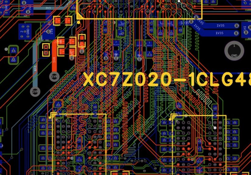
PCB Layout: Escaping the BGA Without Losing Your Mind
Your schematic is a promise. Your PCB is where you find out if you lied.
With a Zynq BGA, layer count and via strategy are not “nice-to-have discussions”they are the routing plan.
Use established BGA design rules for pad/via/trace dimensions, breakout patterns, and fabrication constraints.
Decide early whether you’re using standard vias, microvias, via-in-pad, or a hybrid approach, because that choice affects cost and yield.
Layout priorities (in the order your future self will thank you for)
- Power distribution and decoupling placement (close, low-inductance, and aligned with current loops)
- DDR placement and routing (stackup confirmed, constraints defined, matching strategy decided)
- Clocks and resets (short, clean, and away from noisy switching nodes)
- High-speed interfaces (USB ULPI, Ethernet, HDMI differential pairs)
- Everything else (GPIOs, headers, LEDs, “the fun stuff”)
A lot of builders aiming for cost control choose a compact board size (think roughly 100 mm square) and accept that an 8-layer or even 10-layer PCB
may be a practical necessity once you include DDR, BGA escape routing, and clean reference planes. That can still be financially reasonable for prototypes
especially if you keep the first revision focused and avoid over-populating optional features.
Bring-Up: A Calm, Repeatable Plan Beats Heroics
Bring-up is not the time for freestyle. It’s the time for checklists, test points, and measured confidence.
The goal is to prove subsystems one at a time, in an order that narrows your failure space quickly.
A staged bring-up flow
- Stage 1: Power sanity Verify each rail voltage, ramp behavior, and ripple. Check for hot parts.
- Stage 2: JTAG connection Confirm you can see the device and communicate reliably.
- Stage 3: Basic PS life signs UART output, basic boot attempts, strap verification.
- Stage 4: DDR validation If DDR is unstable, Linux will be a comedy of errors.
- Stage 5: Boot chain BootROM → FSBL → U-Boot → kernel (and only then celebrate).
- Stage 6: Peripherals USB, Ethernet, display, audio, and the rest.
When you reach the “boot Linux” milestone, you’ll likely touch PetaLinux (or a similar flow) and the classic early boot components like an FSBL.
This is where strong hardware decisions pay off: correct boot media wiring, reliable clocks, clean DDR, and debug access.
Common Pitfalls (A.K.A. Things That Have Ruined Many Saturdays)
- Underestimating decoupling and return paths: The board “works” until load transients happen.
- Boot mode straps wrong or ambiguous: You think you’re booting SD, but the chip thinks you’re booting vibes.
- DDR routing without constraints: “It looks tidy” is not a timing spec.
- USB ULPI layout sloppiness: Parallel high-speed nets punish wishful thinking.
- Ethernet layout shortcuts: EMI, link instability, and mysterious packet loss await.
- No test points: Debug becomes interpretive dance instead of engineering.
- Too many features in Rev A: Complexity doesn’t scale linearly; it multiplies.
Final Thoughts: The Point Isn’t to “Compete” With Commercial Dev Boards
Building a custom Zynq-7000 development board isn’t about proving you can out-design a company that has shipped thousands of boards.
It’s about learning the craft and creating a platform tailored to your goals: your connectors, your peripherals, your constraints, your workflow.
Hackaday’s spotlight on a full board build (from power to HDMI to Linux boot) captures the real value here: the educational arc.
You don’t just end up with a boardyou end up with the kind of hard-earned understanding that makes future projects faster, cleaner, and less scary.
Field Notes: What “From the Ground Up” Feels Like in Practice (500+ Words)
If you want the honest emotional timeline of building a custom Zynq-7000 dev board, it goes something like this:
Week 1: “This is going to be awesome.” Week 2: “Why does this chip need so many power pins?”
Week 3: “I have learned new words, like ‘PDS,’ ‘return path,’ and ‘via escape,’ and I miss who I used to be.”
The most useful “experience lesson” builders report is that you don’t really design one boardyou design a sequence of boards.
The first revision is rarely perfect, and that’s normal. In one publicly documented build journey associated with the Hackaday feature, the designer
set a clear learning-first goal, targeted a compact board size for cost containment, and accepted that an 8–10 layer stackup might be necessary.
That framing matters, because it turns inevitable iteration into part of the plan instead of an emergency.
Another very real experience: parts availability and substitutions are not theoretical problems. They’re Tuesday.
Even when you choose components from major distributors, you may end up swapping capacitor values or picking alternate regulators because of stock,
price, or what you already have in the lab. Builders often find that the board can still run “well enough” with sensible substitutionsbut
those substitutions become technical debt. The board boots today, but you still want to revisit the BOM later with more appropriate bulk capacitance
and a cleaner, more intentional power design once the platform proves itself.
The bring-up experience is also surprisingly psychological. The first time you power the board, you’re not “testing the design” so much as
“discovering your assumptions.” You learn quickly to love three things:
(1) current-limited bench supplies, (2) thermal cameras or at least a careful fingertip check (with caution), and (3) labeled test points.
When a rail is low, you don’t want to guessyou want to measure, isolate, and move forward.
Debug access becomes your emotional support animal. JTAG isn’t optional in spirit, even if it’s optional in production.
Having a reliable path to talk to the deviceplus a UART console so you can see what boot stages are happeningturns “dead board”
into “board with one specific problem,” which is a vastly more solvable situation.
Peripherals are where experience saves you from the “it’s always software” trap. USB and Ethernet can fail for layout reasons that look like driver bugs.
HDMI can fail because one differential pair is slightly worse than its neighbors, or because hot-plug/EDID handling is incomplete.
The experienced move is to validate in layers: prove the core system (power, clocks, DDR, boot) first, then add one peripheral at a time with
focused tests and known-good reference configurations.
And finally, the most satisfying experience moment is also the least glamorous: the first time you boot a real Linux userspace on hardware you created.
Not an eval kit. Not a known reference design. Your board. Even if performance isn’t perfect and you still have a long punch list,
that milestone changes how you think about hardware. It’s no longer magicit’s a process. A challenging one, sure, but repeatable.
After that, future board designs stop feeling like cliffs and start feeling like ladders.