
Table of Contents >> Show >> Hide
- What “Automatic I2C Address Allocation” Actually Means
- Why Daisy-Chained Sensors Are So Often a Problem
- The Most Practical Ways to Implement Automatic Address Allocation
- A Reference Boot Strategy That Works Well
- Design Rules That Save You From Future Regret
- Specific Examples of Good Architecture Choices
- Experiences From Building Automatic I2C Address Allocation Systems
- Final Thoughts
Here is the big dream: you snap together a chain of sensors, power the system, and every device politely picks its own I2C address like guests choosing name tags at a conference. No solder jumpers. No mysterious 0x29 traffic jam. No midnight debugging session where the logic analyzer becomes your emotional support animal.
Reality is slightly less magical. I2C is brilliant, simple, cheap, and everywhere, but it was not born as a plug-and-play discovery bus. It was built to let one controller talk to multiple targets over two wires, with each device already having a unique address. That is why automatic I2C address allocation for daisy-chained sensors is not a single built-in feature. It is a design pattern. Sometimes it is a clever one. Sometimes it is a little duct tape wearing a firmware hat.
This article explains what automatic address allocation really means, why it matters for daisy-chained sensors, which methods work best in practice, and how to build a system that survives both production and human curiosity. Along the way, we will look at boot sequencing, address-pin control, I2C multiplexers, sideband enumeration, and the kind of lessons engineers usually learn only after saying, “Wait, why are all eight sensors answering at once?”
What “Automatic I2C Address Allocation” Actually Means
In plain English, automatic address allocation means this: a group of sensors that initially share the same default I2C address somehow become uniquely addressable at startup without requiring the installer to manually configure each board.
That “somehow” matters. Base I2C gives you addressing, acknowledgments, open-drain signaling, reserved address ranges, and optional behaviors like general call support. What it does not give you is a universal USB-style enumeration routine where each new device introduces itself, receives a fresh address, and joins the party in order.
So when engineers talk about automatic address allocation on I2C, they usually mean one of four practical approaches:
- Bring sensors online one at a time and assign each a new address during boot.
- Drive hardware address pins from a controller so addresses are set dynamically.
- Hide identical sensors behind a multiplexer or switch so they can keep the same address.
- Add a sideband signal or token-passing scheme so a chain can self-enumerate physically.
All four approaches can work. The best one depends on whether your sensors support address changes, how many modules you plan to chain, whether the chain must be hot-pluggable, and how much extra hardware you are willing to tolerate.
Why Daisy-Chained Sensors Are So Often a Problem
Daisy-chain connectors are convenient, not magical
Systems like Qwiic and STEMMA QT make I2C feel delightfully civilized. You get compact four-wire connectors, less wiring error, and boards that can be physically chained one after another. That is excellent for prototyping and fast assembly.
But the electrical truth is still the same: all those connected boards usually share the same SDA and SCL bus. In other words, physical daisy-chaining does not create separate communication lanes. It creates one larger shared neighborhood. If two identical sensors boot at the same default address, they will both answer together, and the controller will hear a digital chorus instead of a clean solo.
Addresses are limited, and some are reserved
Most everyday I2C devices use 7-bit addressing. That sounds roomy at first, but some addresses are reserved, and many sensors expose only one or a few legal address options. A temperature sensor that lets you choose between only 0x48 and 0x49 is not exactly running a real-estate empire.
That is why identical sensors often collide. The bus can support many devices, but only if each one can be uniquely addressed. If not, you need a system-level workaround.
The bus gets electrically grumpy as it grows
I2C is open-drain, which means pull-up resistors and bus capacitance matter. Add more cables, more connectors, more boards, more pull-ups, and suddenly rise times slow down, edges soften, and reliability starts acting like it needs a weekend off. Daisy-chained sensor systems fail not only because of address conflicts, but also because of bus loading, mixed voltage domains, bad pull-up choices, and excessive capacitance.
So a scalable design must solve both identity and signal integrity. Fix only one, and the other will eventually send you an invoice.
The Most Practical Ways to Implement Automatic Address Allocation
1. Boot sequencing with enable or reset pins
This is the workhorse method, and for many products it is the best answer. If each sensor has an enable, reset, shutdown, or chip-enable pin, the controller holds all of them inactive at power-up. Then it brings them online one at a time.
The flow is simple:
- Keep all sensors disabled.
- Enable sensor 1. It appears at the default address.
- Write a new address into its configuration register.
- Leave sensor 1 active.
- Enable sensor 2, which still boots at the default address.
- Assign it a different address.
- Repeat until all sensors are uniquely addressed.
This is how many developers handle multiple identical time-of-flight sensors such as VL53L0X-class devices. The catch is important: some sensors only keep the reassigned address until reset or power loss. That means the controller must repeat the allocation sequence on every cold boot. Annoying? A little. Reliable? Usually yes.
This approach is ideal when the controller has enough GPIOs, boot order is predictable, and devices do not need to be swapped live while the system is running.
2. Dynamic control of hardware address pins
Some I2C parts expose address-select pins like A0, A1, and A2. On many breakout boards, those are normally tied with solder jumpers. In a smarter design, the controller can drive those lines directly through GPIOs or a small latch, setting each device’s address at startup.
This method is elegant because the address becomes deterministic. You can define, for example, that module slot 0 gets address 0x40, slot 1 gets 0x41, and so on. It also avoids writing volatile address registers in software if the device reads its address pins continuously or latches them at boot.
The downside is board complexity. Each device needs extra traces, and not every sensor supports enough address-pin combinations to scale very far. Still, for short chains and fixed layouts, this is a beautifully practical solution.
3. I2C switches and multiplexers
Sometimes the sensor will not let you change its address at all. In that case, the honest answer is: stop trying to make the sensor become someone else. Put it behind a multiplexer or switch instead.
With an I2C multiplexer, the controller selects one downstream channel at a time. Each identical sensor can stay at the same default address because only one branch is visible during a transaction. This is not true address allocation, but from the firmware’s perspective it often feels close enough.
Multiplexers shine when you have lots of identical parts, when address reassignment is volatile, or when you need to isolate branches to reduce capacitive loading. The tradeoff is extra hardware, extra firmware steps, and one more component whose own address must not collide with something else. Engineering never misses an opportunity to add a sequel.
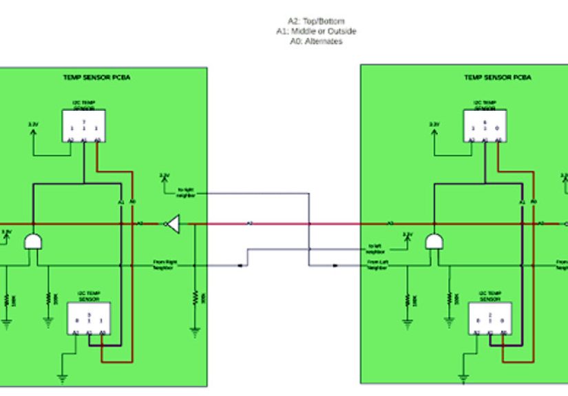
4. Sideband token passing for true chain discovery
If you are designing the sensor modules yourself, the cleanest plug-and-play scheme is usually a sideband enumeration line. Each module has an input token and an output token. On reset, only the first unassigned board in the chain sees the token. That board temporarily enables its I2C interface at the default address, receives a new address from the controller, stores it, then forwards the token to the next board.
This creates a true physical-order discovery process. The controller can assign addresses based on chain position, and the system scales nicely without burning a dedicated reset pin per sensor.
This is often the best architecture for custom daisy-chained sensor modules in robotics, industrial sensing, lighting, and wearable hardware. It adds one more wire or connector pin, but that extra pin usually saves a mountain of firmware pain later.
A Reference Boot Strategy That Works Well
For a custom chain of identical sensors, a robust startup design often looks like this:
- All modules power up in an unassigned state.
- Only the first module exposes its default I2C address.
- The controller queries the module, optionally reads a unique ID if available, and assigns a new operational address.
- The module stores the assigned address in RAM or nonvolatile memory, depending on device capability.
- The module passes an enumeration token to the next board.
- The controller repeats until no additional module responds.
- The system performs an address scan and starts normal measurements.
This pattern gives you deterministic ordering, low ambiguity, and painless replacement behavior. If module three dies and is replaced, the chain can simply re-enumerate at the next boot. No soldering iron, no cursed spreadsheet of address jumpers, no sticky note that says “green board is 0x46 unless Karen swapped it.”
Design Rules That Save You From Future Regret
Keep pull-ups under control
Many breakout boards include their own pull-up resistors. Chain enough boards together and the effective pull-up becomes much stronger than intended. That can distort timing, increase current draw, and make debugging far less fun than the datasheet promised. Decide where the primary pull-ups live, and be deliberate.
Plan for bus capacitance early
Long cables and many modules increase capacitance. If your chain is physically large, consider slower bus speeds, bus buffers, or segmented architecture. A design that works on the bench with three boards can become very dramatic with twelve boards and a cable harness.
Make startup deterministic
Race conditions are the natural predator of automatic allocation. Ensure modules start in a known state, define who is allowed to answer first, and avoid relying on vague timing luck. “Usually boots fine” is engineer-speak for “future support ticket.”
Use an address scanner during bring-up
Simple I2C scanner tools are invaluable during development. They help verify whether one device, many devices, or absolutely nobody is answering. That sounds basic because it is basic, and basic tools save advanced embarrassment all the time.
Specific Examples of Good Architecture Choices
Best for hobby and prototype chains: per-device shutdown pins plus firmware address assignment. It is easy to understand, easy to debug, and works with many off-the-shelf sensor boards.
Best for fixed production assemblies: controller-driven address pins. It gives deterministic addressing with minimal boot chatter.
Best for many identical sensors: an I2C multiplexer or switched tree. It avoids address fights completely and can improve electrical robustness.
Best for custom modular chains: sideband token enumeration plus optional unique ID storage. This is the closest thing to a real plug-and-play experience on plain I2C.
Experiences From Building Automatic I2C Address Allocation Systems
The first time you build a daisy-chained I2C sensor system, it feels wonderfully efficient. Two wires for data, one connector style, neat little boards snapped together in a line, and just enough early success to make you overconfident. Then you add the second identical sensor, and suddenly the bus behaves like two people answering the same phone at the same time. You send one command, both devices acknowledge, and the returned data looks less like measurement and more like electronic improv comedy.
One of the most common experiences is discovering that “automatic” rarely means “no design effort.” It usually means the hard work moved from the installer to the hardware and firmware team. That is still a good trade, but only if the design is intentional. Engineers often start by trying to change each sensor’s address in software after boot, only to learn that every device wakes up at the same default address and hears the same command. That is the moment when reset pins, enable pins, or multiplexers stop looking optional and start looking like friends.
Another recurring lesson is that physical order matters more than people expect. When modules are connected in a chain, users naturally assume the first sensor in the cable path will become sensor 1 in firmware. If the design does not guarantee that relationship, support gets weird fast. Someone points at the third module, the software reports the fifth, and everybody loses ten minutes of life they will never get back. Token-passing or one-at-a-time enable control solves this beautifully because it aligns electrical discovery with physical order.
There is also the pull-up resistor surprise. On paper, each breakout board helpfully includes pull-ups. In a large chain, those “helpful” resistors can gang up like an overenthusiastic committee. The result is a bus that might work on one controller, fail on another, and become unreliable only when the cable length changes by what seems like a completely insulting amount. Many real-world I2C stories end with someone muttering, “It was the pull-ups,” as if naming the villain in the final scene of a detective movie.
Hot-plugging is another place where theory and experience have a spirited disagreement. Teams often imagine users adding a sensor module while the system is live and the software calmly discovering it. Plain I2C can support impressive systems, but hot-swap friendliness does not happen by wishing really hard. If live insertion matters, you need buffering, controlled startup states, and a plan for re-enumeration that does not confuse devices already on the bus.
The best experience, though, comes when the architecture finally clicks. You power the chain, watch each module claim a unique address in order, run a scan, and see a perfect list of responses. It is a very satisfying moment because the solution feels simple after you have done the hard thinking. That is usually the sign of good embedded design: not that the problem was easy, but that the finished system makes the complexity look well-mannered.
Final Thoughts
Automatic I2C address allocation for daisy-chained sensors is absolutely achievable, but it is not a free gift from the protocol. The safest mindset is to treat I2C as a shared bus that needs help with identity. Once you accept that, the solution becomes clearer.
If the sensors have shutdown pins, sequence them. If they have address pins, drive them. If they cannot change addresses, isolate them with a mux. If you are designing a custom chain, add a sideband enumeration method and never look back. Combine that with good pull-up discipline, bus-capacitance awareness, and deterministic startup behavior, and your sensor chain will behave like a professional subsystem instead of a small digital rebellion.
And that, in embedded systems, is about as close to romance as we get.