Table of Contents >> Show >> Hide
- What Is a GBA Multiboot Cable?
- How Game Boy Advance Multiboot Works
- Parts Needed for an Arduino Based Multiboot Cable
- Typical Wiring for the GBA Link Port
- Software Workflow: From Code to Real Hardware
- What Can You Build With a GBA Multiboot Cable?
- Common Problems and How to Fix Them
- Best Practices for a Reliable Arduino GBA Multiboot Cable
- Arduino Based Multiboot Cable vs Flash Cartridge
- Practical Experience: Building and Using an Arduino Based Multiboot Cable for Game Boy Advance
- Conclusion
- SEO Tags
The Game Boy Advance may look like a charming little handheld from the early 2000s, but under that plastic shell is a surprisingly serious development target: a 32-bit ARM7TDMI CPU, a 240-by-160 color display, real hardware registers, and just enough quirks to keep a weekend electronics project from becoming boring. An Arduino based multiboot cable for Game Boy Advance is one of those wonderfully nerdy bridges between modern tinkering and retro hardware. It lets a computer send homebrew code to a real GBA through the link port, often without needing a flash cartridge.
In plain English, this cable turns an Arduino into a translator. Your PC speaks USB serial. The Game Boy Advance expects a very specific link-port conversation. The Arduino stands in the middle wearing a tiny diplomatic hat, moving bits in the right order, at the right voltage, and with the right timing. Do it well, and your own demo, test ROM, or tiny game boots on actual hardware. Do it badly, and the GBA politely shows you a blank screen, which is retro hardware’s way of saying, “Nice try, champ.”
What Is a GBA Multiboot Cable?
A GBA multiboot cable is a hardware-and-software setup that sends a small program to a Game Boy Advance over its external link port. Nintendo designed multiboot for single-cartridge multiplayer. One console could host a game, and other connected GBAs could download a smaller client program into RAM. Homebrew developers later realized this was also a practical way to test code on real hardware.
The key limitation is size. Traditional multiboot payloads must fit into the GBA’s work RAM, so projects are commonly limited to about 256 KB. That is not much by modern standards; one high-resolution phone photo can laugh at 256 KB. But for GBA homebrew, it is enough for “Hello World,” sprite tests, music experiments, tech demos, BIOS dumping utilities, link-port experiments, and small games if the programmer is disciplined.
Why Use Arduino Instead of a Simple USB Cable?
The GBA link port is not USB. It uses serial communication modes that require specific timing and signal behavior. A plain cable cannot magically convert USB packets into the GBA’s expected serial handshake. An Arduino, Teensy, Nano 33 BLE, or similar microcontroller can receive data from a computer, then drive the GBA’s link lines in a controlled way.
That microcontroller role is the heart of the project. It is not just “wire this pin to that pin and hope.” The Arduino must participate in the boot process, send data in a form the GBA BIOS accepts, and avoid electrical mistakes. This is where retro console development becomes part programming, part electronics, and part detective work.
How Game Boy Advance Multiboot Works
When a GBA starts without a cartridge, or when certain button combinations are used with compatible setups, the system can wait for code through the link port. The receiving console stores the downloaded program in RAM and then executes it. The uploaded file still needs a proper GBA-style header and a valid multiboot layout. It is not enough to toss random bytes at the handheld and expect fireworksunless the fireworks are metaphorical and smell faintly of debugging frustration.
The Role of the BIOS
The Game Boy Advance BIOS contains support for multiboot behavior. In original commercial use, this allowed a main cartridge to send a smaller program to other units. In homebrew use, a computer and microcontroller can imitate the host side. The payload is transmitted through the link port, checked, placed in memory, and started.
The 256 KB Reality Check
A multiboot project should be designed with size in mind. Large bitmap graphics, uncompressed audio, oversized libraries, and careless asset choices can push a ROM beyond the practical limit quickly. Developers often begin with small test programs: a colored screen, a moving sprite, a button input test, or a tilemap demo. Once the cable works reliably, more ambitious projects can follow.
Normal Mode, MultiPlay Mode, and Timing
The GBA link port supports multiple communication styles. Some projects use normal serial mode, which resembles SPI-like communication and can be faster for one target device. Others work through multiplayer-style communication, which is useful in different contexts but may be slower or more complex. In either case, timing matters. Microcontroller code that is too slow, too jittery, or written with overly high-level pin toggling may fail in mysterious ways.
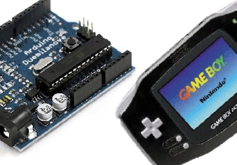
Parts Needed for an Arduino Based Multiboot Cable
The exact parts vary by build, but a typical project includes a microcontroller, a GBA link cable connector, jumper wires, a logic level shifter, and software tools on the computer. You do not need a laboratory that looks like a superhero’s basement. You do need patience, clean wiring, and a healthy respect for voltage levels.
Common Hardware List
- Arduino-compatible board: Arduino Nano, Uno, Pro Micro, Nano 33 BLE, Teensy, or another microcontroller with reliable serial and SPI-style I/O.
- GBA link cable plug: Often salvaged from an old Game Boy Advance link cable.
- Logic level converter: Strongly recommended when using 5V Arduino boards with 3.3V GBA signals.
- USB cable: Connects the Arduino to the computer.
- Wires and headers: For connecting SO, SI, SC, GND, and sometimes SD.
- Computer: Used for compiling homebrew and sending the multiboot payload.
- Development tools: devkitARM, libgba examples, PlatformIO, Arduino IDE, Make, or project-specific transfer tools.
Voltage: The Tiny Detail That Can Ruin the Party
Many classic Arduino boards, including the Arduino Uno Rev3, operate at 5V logic. The Game Boy Advance link port expects 3.3V logic. Some old writeups casually connected 5V outputs to the GBA and got away with it, but “it worked once on somebody’s desk in 2010” is not a protection circuit. A proper level shifter or a native 3.3V board is the smarter choice.
A board such as the Arduino Nano 33 BLE operates at 3.3V, which makes it attractive for this kind of project. If you use a 5V Arduino, add bidirectional level shifting where needed. At minimum, avoid feeding 5V signals directly into the GBA’s input pins. The console is vintage hardware now; treat it like a beloved old sports car, not a rental scooter.
Typical Wiring for the GBA Link Port
The GBA link port uses several named lines. The important ones for many multiboot cable designs are SO, SI, SC, SD, and GND. In normal serial mode, SO and SI cross between host and target, SC carries the serial clock, and GND provides the shared reference. Some builds leave SD unused; others use it for specific transfer modes or detection behavior.
Common Signal Mapping
| GBA Signal | Typical Role | Arduino-Side Concept |
|---|---|---|
| SO | Serial out from GBA | MISO or input line |
| SI | Serial input to GBA | MOSI or output line |
| SC | Serial clock | SCK or clock line |
| SD | Mode/data line in some protocols | Optional GPIO depending on design |
| GND | Ground reference | Arduino GND |
Wire colors are not universal. A cable that looks official may still have crossed or unexpected colors depending on which end you cut. Always verify pin positions with a continuity test rather than trusting red, orange, blue, or green wires like they are sworn witnesses in court.
Power Connection Warning
In many projects, the Arduino is powered from USB, not from the GBA. The GBA link port has a 3.3V line, but that does not mean it should power your entire microcontroller setup. Keep the power arrangement simple: Arduino from USB, GBA from its own batteries or adapter, and grounds connected together.
Software Workflow: From Code to Real Hardware
The software side usually has three layers. First, you write or compile a GBA homebrew program. Second, you prepare it as a multiboot-compatible payload. Third, a PC-side sender talks to the Arduino, and the Arduino talks to the GBA.
Step 1: Build a Small GBA Program
Most developers begin with devkitARM and libgba examples. A basic first program might initialize the display, set a video mode, and draw a colored screen. This confirms that your compiler, linker script, startup code, and emulator testing process are working. Before touching wires, run the ROM in an emulator such as mGBA. If the file does not work in an emulator, the cable is not going to sprinkle fairy dust on it.
Step 2: Make It Multiboot-Friendly
A cartridge ROM and a multiboot payload are related but not identical. Multiboot code runs from RAM rather than the cartridge address space. That affects memory assumptions, linker settings, entry points, and size limits. Some repositories include templates that handle these details. Using a proven template is wise, especially for a first build.
Step 3: Flash the Arduino Firmware
The Arduino needs firmware that understands the transfer process. In many open-source examples, the sketch or PlatformIO project receives bytes from a PC utility and then performs the GBA-side signaling. This code is timing-sensitive. Replacing carefully written port operations with slow convenience calls may break the transfer.
Step 4: Send the Payload
Once the Arduino firmware is loaded and the cable is wired, the PC-side sender transmits the GBA file. Some workflows use a command-line tool where you specify the serial port and the file name. The GBA should be powered on in the right boot state, then the transfer begins. When everything works, the Nintendo logo process completes, the payload lands in RAM, and your program appears on the screen.
What Can You Build With a GBA Multiboot Cable?
The obvious answer is “homebrew games,” but the better answer is “small experiments that teach you how the GBA really works.” A multiboot cable is perfect for rapid hardware testing because it reduces dependence on flash cartridges. You can compile, send, test, tweak, and repeat.
Good First Projects
- Hello World screen: Print text or draw a simple background.
- Button tester: Show which GBA buttons are being pressed.
- Sprite demo: Move a sprite around the screen with the D-pad.
- Audio test: Play a short tone or sample if your payload size allows it.
- Link-port experiment: Explore communication between devices once the basics work.
- BIOS or hardware diagnostics: Carefully written utilities for learning and preservation.
Projects That Need More Planning
Larger games, asset-heavy demos, or projects with big soundtracks may exceed multiboot limits. You can still use the cable for small loaders, testing routines, or early prototypes, but a flash cartridge or different loading method may be better for full-scale development. Think of multiboot as a nimble bicycle, not a moving truck.
Common Problems and How to Fix Them
Blank Screen After Transfer
A blank screen can mean many things: the payload is not multiboot-compatible, the entry point is wrong, the ROM is too large, the transfer failed, or the program started and immediately crashed. Test the same build in an emulator, then confirm the linker script and header requirements.
Random Transfer Errors
Random errors often point to timing or wiring. Long wires, poor grounding, slow bit-banging code, or missing level shifting can create unstable behavior. Keep wires short, verify continuity, use a stable clock approach, and avoid slow digital I/O functions in tight transfer loops.
Nothing Happens at All
If the GBA never responds, check the boot state, cable orientation, pin mapping, and serial port selection. Make sure the Arduino firmware is actually running and that the PC sender is connected to the correct device. Also confirm that ground is shared. Electronics without a common ground are basically two people arguing in different languages across a river.
Works Once, Then Fails
Intermittent success can be caused by marginal voltage levels, loose connectors, noisy wiring, or a boot timing sequence that is not reliable. Rebuild the cable more cleanly, add proper level shifting, and simplify the test payload. Debug with the smallest possible program before blaming the entire universe.
Best Practices for a Reliable Arduino GBA Multiboot Cable
A reliable build is usually boring in the best way. It has short wires, clean solder joints, clear labels, and a known-good firmware version. The more “temporary” the wiring looks, the more permanent your frustration may become.
Use a 3.3V-Safe Design
Choose a native 3.3V microcontroller when possible. If using an Arduino Uno or classic Nano, add a level converter. This protects the GBA and improves signal compatibility.
Label the Connector
GBA link plugs are small, and pin orientation can be confusing. Label the cable end after verifying each pin. A tiny paper tag today can save an hour of squinting tomorrow.
Start With Proven Code
Use known working open-source firmware, templates, and sender tools before writing your own protocol code. Once you have a successful baseline, experiment freely. Changing everything at once is how projects become archaeological mysteries.
Keep Payloads Small
Compress assets, remove unused libraries, and avoid bloated debug code. Multiboot rewards minimalism. If your tiny demo has a file size that looks like a desktop app, something has gone off the rails.
Arduino Based Multiboot Cable vs Flash Cartridge
A flash cartridge is more convenient for larger GBA projects. It can run bigger ROMs and often behaves more like a normal cartridge. However, an Arduino based multiboot cable is cheaper, more educational, and more satisfying for developers who enjoy understanding the hardware path from PC to console.
When the Cable Makes Sense
Use a multiboot cable when you want to test small programs, learn the link protocol, experiment with real hardware, or build a low-cost development tool. It is also useful for classrooms, workshops, and hobbyists who want to introduce embedded systems through a familiar gaming device.
When a Flash Cart Is Better
Use a flash cartridge when your project is large, asset-heavy, or needs save memory and cartridge-like behavior. A multiboot cable is not a universal replacement. It is a specialized tool, and that specialization is exactly what makes it interesting.
Practical Experience: Building and Using an Arduino Based Multiboot Cable for Game Boy Advance
The first practical lesson is that this project feels simple right up until it does not. On paper, the cable is only a few wires. In reality, every wire has a job, every signal has timing requirements, and every assumption about color coding deserves suspicion. The best experience comes from treating the project like a tiny engineering build rather than a casual craft project.
Start by preparing the software before soldering anything. Install the GBA toolchain, compile a tiny multiboot example, and test it in an emulator. A good first target is a screen that turns blue, prints a short message, or moves one sprite. Keep it boring. Boring is beautiful when you are debugging hardware. Once the ROM works in an emulator and its size is comfortably under the limit, move to the cable.
For wiring, the most useful habit is documenting the cable as you build it. Draw the GBA connector, mark the pin numbers, and write down where each pin goes on the Arduino. Do not rely on memory. Memory is great for birthdays and song lyrics, but terrible for remembering whether the green wire was SI or SC after three cups of coffee. A multimeter continuity test is your best friend. Use it before soldering, after soldering, and again when something behaves oddly.
Level shifting is another place where experience teaches humility. Some builders have reported success with direct 5V connections, but that does not make it good practice. A 3.3V-safe board or a proper logic level converter removes a major risk. Retro consoles are no longer cheap disposable gadgets; they are aging hardware with sentimental and collector value. Protecting the GBA is worth the few extra minutes.
Once everything is connected, expect the first transfer to fail. That is not pessimism; that is tradition. Check the serial port, confirm the Arduino firmware, reset the GBA into the correct state, and send the smallest payload. If the screen stays blank, do not immediately rewrite the whole program. Check ground, pin orientation, payload size, and whether SO and SI are crossed correctly. Most failures are not dramatic. They are small, ordinary mistakes wearing fake mustaches.
The best moment is the first successful boot. A simple test screen appearing on real GBA hardware feels far more exciting than it should. Suddenly, the handheld is not just a nostalgic console; it is a development board with buttons, sound, a display, and a personality. After that, the cable becomes a fast learning loop. You can test graphics modes, input handling, interrupt timing, tilemaps, sprites, and link-port behavior on the machine itself.
The main long-term tip is to keep a stable “known good” setup. Save the working Arduino firmware, the working sender tool, the working test ROM, and a wiring diagram. When you later experiment with faster transfer modes or custom protocol code, you can always return to the baseline. That baseline is the difference between productive tinkering and staring at a blank screen while questioning all your life choices.
Conclusion
An Arduino based multiboot cable for Game Boy Advance is more than a retro computing trick. It is a hands-on lesson in embedded development, serial communication, voltage safety, homebrew tooling, and the delightful stubbornness of classic hardware. By using an Arduino as a bridge between a modern computer and the GBA link port, developers can upload small programs directly into RAM and test code on real hardware without immediately buying a flash cartridge.
The project is not difficult because it uses many parts; it is difficult because the details matter. The right pin mapping, proper 3.3V logic, correct payload format, careful timing, and small ROM size all work together. Get those right, and the Game Boy Advance becomes a compact ARM development playground. Get them wrong, and the console becomes a tiny black-screen philosopher asking, “But did you check the ground?”
For homebrew developers, electronics hobbyists, and retro gaming fans, this cable is a rewarding build. It teaches patience, rewards careful testing, and gives old hardware a new creative purpose. Best of all, the first time your own code boots on a real GBA, the whole project instantly feels worth the solder fumes.