
Table of Contents >> Show >> Hide
- What This Guide Covers
- Tools and Parts You May Need
- How to Wire a Variable or Fixed Speed DC Motor Circuit
- Step 1: Identify the motor type and nameplate ratings
- Step 2: Decide whether you need fixed speed or variable speed
- Step 3: Choose a DC power supply that matches the motor
- Step 4: Size the wire for current and cable length
- Step 5: Add a fuse near the power source
- Step 6: Plan the circuit path before making any connection
- Step 7: Disconnect all power and make the workspace safe
- Step 8: Wire the negative return first
- Step 9: Wire the positive feed through the fuse
- Step 10: Build the fixed-speed branch if you want simple on/off operation
- Step 11: Build the variable-speed branch with a PWM controller
- Step 12: Add flyback protection or confirm the driver includes it
- Step 13: Add reversing control if needed
- Step 14: Separate power wiring from control wiring
- Step 15: Test slowly, measure everything, and troubleshoot methodically
- Common Wiring Mistakes to Avoid
- Real-World Experiences Wiring DC Motor Circuits
- Conclusion
- SEO Tags
If you have ever stared at a DC motor, a handful of wires, and a speed controller that looks like it belongs in a tiny spaceship, welcome to the club. Wiring a variable or fixed speed DC motor circuit is not wizardry, but it does reward patience, correct parts, and a healthy fear of “just trying it and seeing what happens.” That method usually ends with a hot wire, a blown fuse, or a smell that suggests your project has entered its final form.
This guide walks through how to wire a typical two-wire brushed DC motor for either fixed-speed or variable-speed operation in 15 clear steps. You will learn how to choose the right power supply, protect the circuit, wire a switch or PWM speed controller, and test everything without turning your workbench into an accidental smoke machine. Whether you are building a small fan, conveyor, hobby machine, actuator project, or simple workshop mechanism, the core process is the same: match voltage, respect current, protect the circuit, and test in stages.
What This Guide Covers
This article focuses on low-voltage brushed DC motors, the kind commonly used in hobby electronics, shop tools, small machines, actuators, and DIY equipment. If your motor has more than two main motor leads and requires a dedicated electronic commutation system, that is usually a brushless DC motor and needs a different type of controller. In other words, if your motor is more “smart machine” than “simple spinny thing,” do not wire it like the one in this guide.
Tools and Parts You May Need
- Brushed DC motor
- Correct DC power supply or battery
- On/off switch or reversing switch
- PWM DC motor speed controller for variable speed
- Fuse or circuit breaker
- Appropriately sized wire
- Crimp terminals, ferrules, or soldered connectors
- Multimeter
- Heat shrink tubing or electrical insulation
- Mounting hardware and cable ties
How to Wire a Variable or Fixed Speed DC Motor Circuit
Step 1: Identify the motor type and nameplate ratings
Start by reading the motor label or datasheet. You need the rated voltage, running current, and, if possible, the stall current. The rated voltage tells you what supply the motor expects. The current tells you what your wire, fuse, switch, and controller must survive. The stall current matters because motors draw their highest current at startup or when jammed. Ignore that number, and your “working circuit” may last just long enough for you to feel confident.
If the datasheet is missing, measure carefully and proceed conservatively. Never assume a random 12V motor can be happy on any 12V supply without checking current capability.
Step 2: Decide whether you need fixed speed or variable speed
A fixed speed DC motor circuit is the simpler setup. The motor gets full supply voltage through a switch or relay, so it runs at roughly one operating speed determined by the motor, load, and supply voltage.
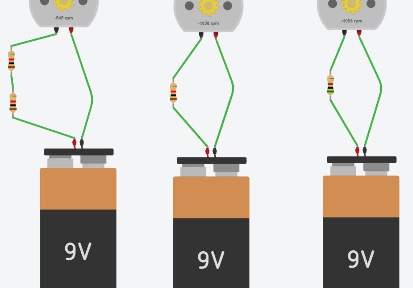
A variable speed DC motor circuit uses a controller, usually a PWM controller, to vary the effective power delivered to the motor. PWM, or pulse-width modulation, is popular because it controls speed efficiently without wasting as much energy as crude resistive methods. For most DIY and small-machine projects, PWM is the practical choice.
Step 3: Choose a DC power supply that matches the motor
Your power source must match the motor voltage and supply enough current for startup and load changes. A power supply that is too weak can cause resets, stalling, overheating, or controller shutdown. A battery or DC supply with comfortable current headroom is usually the safer bet.
For example, if you have a 12V motor that normally runs at 3A but can surge higher at startup, a 12V supply rated only 2A is asking for trouble. Pick a supply with enough reserve to handle inrush current and real-world load conditions.
Step 4: Size the wire for current and cable length
Wire size is not just about “will it fit in the terminal.” It affects safety, voltage drop, and performance. Longer wire runs and higher current require thicker conductors. If the wire is too small, the motor may run weakly, the wire may heat up, and troubleshooting becomes a very annoying guessing game.
As a rule, size wire based on both amperage and total run length. For compact bench projects, short runs may allow smaller wire. For longer runs, go heavier. If the motor is near its current limit or the cable run is more than a few feet, do not get cute with thin wire.
Step 5: Add a fuse near the power source
Every DC motor circuit should have overcurrent protection. Place the fuse or breaker on the positive supply lead, close to the power source. That way, if there is a short in the wiring, the protective device can interrupt the fault before the wire becomes the heating element in your new accidental toaster.
Choose a fuse that fits the circuit design and startup characteristics. Time-delay protection is often useful in motor circuits because motors naturally draw higher current at startup. The goal is not nuisance blowing; the goal is meaningful protection.
Step 6: Plan the circuit path before making any connection
Sketch the wiring before you touch the terminals. A basic fixed-speed path looks like this:
Power supply positive → fuse → switch → motor positive lead
Motor negative lead → power supply negative
A basic variable-speed path usually looks like this:
Power supply positive → fuse → PWM controller input positive
Power supply negative → PWM controller input negative
PWM controller output positive/negative → motor leads
If you also want direction control, you may need a reversing switch or an H-bridge controller instead of a one-direction speed control module.
Step 7: Disconnect all power and make the workspace safe
Before wiring anything, disconnect the battery or unplug the DC supply. If the motor is part of a machine, isolate power and prevent unexpected startup. This is the part many people rush, usually right before touching the one conductor they absolutely should not touch.
Keep metal tools away from exposed terminals, and secure the motor so it cannot jump, roll, or twist when power is applied for testing.
Step 8: Wire the negative return first
It is often easiest to begin with the negative side of the circuit. In a fixed-speed setup, connect the motor’s negative lead directly to the power supply negative. In a variable-speed setup, connect the controller input negative to the supply negative, then connect the controller output negative to the motor negative.
Make tight, low-resistance connections. Loose DC motor wiring creates heat, voltage loss, and weird intermittent faults that magically disappear when someone important shows up to inspect your project.
Step 9: Wire the positive feed through the fuse
Now connect the positive supply lead to the fuse holder or breaker input. From the fuse output, continue to the next device in line: the switch for fixed-speed operation or the controller input for variable-speed operation.
This sequence matters. If you place the fuse somewhere random halfway through the circuit, you may leave part of the wiring unprotected. The protective device should guard as much of the positive conductor as possible.
Step 10: Build the fixed-speed branch if you want simple on/off operation
For a fixed-speed motor circuit, connect the fused positive lead to a properly rated on/off switch, relay, or contact device. Then connect the switched output to the motor’s positive lead. Once power is applied and the switch closes, the motor receives full supply voltage.
If the motor spins the wrong direction, reverse the two motor leads. That is one of the nicest things about a simple brushed DC motor: it is not dramatic about direction changes. Swap polarity, and it reverses.
Step 11: Build the variable-speed branch with a PWM controller
For variable speed, wire the fused power leads to the controller’s input terminals exactly as labeled. Then connect the motor to the controller’s output terminals. Most small DC motor speed controllers clearly mark input and motor terminals, but do not assume. Labels beat confidence every time.
Set the speed knob or control signal to minimum before first power-up. Then energize the circuit and increase speed slowly. If the controller supports only one direction, use it for simple speed control. If you want forward and reverse plus variable speed, use a bidirectional controller or H-bridge module designed for brushed DC motors.
Step 12: Add flyback protection or confirm the driver includes it
DC motors are inductive loads. When switching stops current flow, the motor can generate a voltage spike. That spike can damage transistors, switches, or controller electronics if the circuit lacks a safe path for the stored energy.
Many motor drivers and H-bridge controllers include internal protection. If you are switching the motor with a discrete transistor or simple switch arrangement, add the proper flyback suppression recommended for that design. On basic one-direction transistor-switched circuits, a diode across the motor is commonly used. Check orientation carefully, because a backwards diode can turn a clever protection measure into an instant short.
Step 13: Add reversing control if needed
If you need the motor to run both forward and reverse, you have two common choices. One is a reversing switch wired to swap motor polarity. The other is an H-bridge motor driver, which handles direction electronically and often supports PWM speed control at the same time.
This is the point where parts ratings matter a lot. A little hobby driver may be perfect for a desk fan project and laughably underqualified for a gearmotor that behaves like a gym bro at startup. Match the driver’s voltage and peak current ratings to the motor’s real behavior, not your optimism.
Step 14: Separate power wiring from control wiring
Motor circuits can inject electrical noise into control electronics. Keep high-current motor leads short and tidy, and route them away from signal wires where practical. If you are using a microcontroller, use a clean logic supply and good grounding practices. That reduces resets, erratic speed control, and mysterious behavior that makes people blame software for what is really a wiring issue.
For more advanced builds, star grounding, thicker conductors for high-current paths, and decent decoupling near the controller can make the system far more stable.
Step 15: Test slowly, measure everything, and troubleshoot methodically
Once the wiring is complete, double-check polarity, terminal tightness, fuse size, and controller labels. Power the circuit with the motor unloaded if possible. Use a multimeter to verify supply voltage and observe current draw.
If the motor does not run, check these basics first:
- Wrong polarity at the supply or controller input
- Loose terminal screws or poor crimps
- Undersized power supply
- Controller set to zero speed or disabled mode
- Blown fuse
- Motor jammed mechanically
- Driver current rating too low for startup current
If the motor runs hot, the controller screams in protest, or the supply keeps tripping, stop the test and revisit the motor’s current requirements. DC motor circuits are very honest. When something is undersized, they tell you immediately.
Common Wiring Mistakes to Avoid
- Powering the motor from a low-current logic 5V rail
- Skipping the fuse
- Ignoring startup or stall current
- Using a controller with the wrong voltage or current rating
- Running long, thin wires that cause voltage drop
- Forgetting direction control needs polarity reversal or an H-bridge
- Assuming every DC motor controller is reversible
- Wiring a protection diode incorrectly
Real-World Experiences Wiring DC Motor Circuits
The most useful lesson people learn from wiring a variable or fixed speed DC motor circuit is that the circuit on paper is always cleaner than the one on the bench. In real projects, the motor may have a heavier startup load than expected, the supply may sag, the wire run may be longer than planned, and the “temporary” connection may somehow still be there six months later. Experience teaches you to design for reality, not for the perfect version of reality that lives in your sketchbook.
One common experience is building a fixed-speed circuit that seems fine at first, only to discover that the motor starts sluggishly under load. The problem is often not the motor at all. It is usually a weak power supply, an undersized switch, or wire that is too small. Swap in a better supply and heavier conductors, and suddenly the motor behaves like you meant it to all along. This is why experienced builders obsess over current capacity. They are not being dramatic. They have simply smelled enough overheated insulation to earn the right.
Variable-speed circuits add another layer of learning. Many people first assume speed control means “lower the voltage somehow.” Then they try a cheap method that wastes power or gives poor low-speed torque. A proper PWM controller usually solves that issue immediately. The first time you watch a motor start smoothly at low speed without sounding like it is filing a complaint, it becomes obvious why PWM is so widely used.
Another real-world lesson is noise. Not emotional noise, though projects can certainly produce that too. Electrical noise from the motor can disrupt nearby electronics, especially if a controller board or microcontroller shares power poorly. Builders often discover that separating motor power from logic power, improving grounding, and shortening high-current wiring can fix problems that looked like firmware bugs. In many workspaces, the phrase “it was a grounding issue” is practically a personality trait.
Direction control also teaches humility. Reversing a brushed DC motor is simple in theory: swap polarity. In practice, once switches, controllers, safety devices, and enclosures get involved, it becomes easy to mislabel terminals or assume a module does something it does not do. The fix is almost always the same: slow down, read the terminal markings, and test one section at a time.
Perhaps the best experience-based advice is to build cleanly from the start. Label wires. Use proper terminals. Fuse the positive lead near the source. Secure the motor before testing. And never trust a “quick temporary setup” around spinning parts. A neat motor circuit is easier to diagnose, safer to use, and far less likely to surprise you in the worst possible moment. In DC motor wiring, tidy work is not just beautiful. It is practical survival.
Conclusion
Learning how to wire a variable or fixed speed DC motor circuit is really about understanding a few important principles: match the voltage, respect the current, protect the circuit, and choose the right control method. A fixed-speed setup is great when you only need simple on/off operation. A variable-speed setup with PWM is the smarter option when you need control, smoother performance, or better low-speed behavior.
The good news is that once you wire one DC motor circuit correctly, the next one feels far less intimidating. The even better news is that your future self will appreciate the fuse, the proper wire gauge, and the tidy labels when troubleshooting day arrives, because troubleshooting day always arrives.