
Table of Contents >> Show >> Hide
- What a TV Pattern Generator Actually Does (And Why 1981 Needed One)
- Meet the 1981 Vibe: The Philips PM5519 as a Snapshot of the Era
- The Patterns: Why Each One Exists (And What It Diagnoses)
- 1) Crosshatch and Line Grids: Geometry, Linearity, and Dynamic Convergence
- 2) Dot Patterns: Static Convergence’s Best Friend
- 3) Color Bars (and “Bars & Tone” Culture)
- 4) PLUGE: The Tiny Bars That Decide Whether Your Blacks Are Crushed
- 5) Grayscale and Stair Steps: Gamma-ish Reality Checks
- 6) Multiburst: A Frequency Response X-Ray
- 7) Purity Fields (Red/Green/Blue): “Is the CRT Even Happy?”
- How You’d Use a 1981 Pattern Generator in Real Life
- Why This Still Matters in 2026 (Yes, Even With 4K TVs Everywhere)
- Buying (or Rescuing) a Vintage Pattern Generator: What to Look For
- A Quick, Practical Setup Example (No Lab Coat Required)
- Extra: of “Hands-On” Experience With a 1981 Pattern Generator
- Conclusion
There are two kinds of people in this world: (1) those who look at a TV test pattern and feel nothing, and (2) those who look at a TV test pattern and instantly start diagnosing imaginary problems in a CRT that isn’t even plugged in. If you’re still reading, welcome to Group 2.
A TV pattern generator from 1981 isn’t just “a box that makes colorful rectangles.” It’s a time machine to the era when televisions were proudly analog, unapologetically finicky, and gave you exactly zero on-screen error messages. If the picture looked weird, you didn’t open a settings menuyou opened the back of the set, grabbed a plastic alignment tool, and started negotiating with physics.
In this article, we’re checking out what a serious, professional TV pattern generator from 1981 was designed to do, how it produced “known-good” video signals, and why its patterns still make modern video nerds smile. We’ll use the Philips PM5519 family as a representative example of the era: a multi-system color TV pattern generator built for servicing TVs, monitors, VCRs, and related gear, complete with a buffet of patterns and RF modulation that could make it behave like a tiny TV station.
What a TV Pattern Generator Actually Does (And Why 1981 Needed One)
Think of a pattern generator as a truth-teller. It outputs a stable, standardized video signalshapes, lines, bars, grayscales, and burstsso you can stop guessing whether the problem is your TV, your antenna, your VCR, your cables, or the broadcast signal. When you feed your display a “known-good” reference, any ugliness you see is almost certainly your device under testnot the source.
In 1981, that mattered a lot. Color TVs were complex analog systems: geometry could warp, convergence could drift, chroma could misbehave, and timing could get wobbly. TVs didn’t generate internal test patterns. Stations sometimes aired test signals, but you couldn’t count on that at the exact moment you were elbow-deep in a service call. So technicians brought the signal with them.
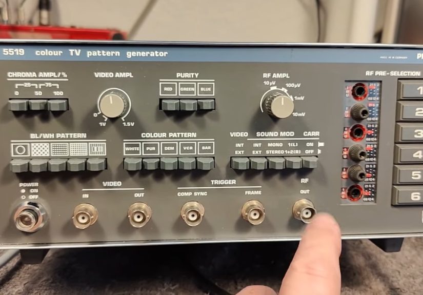
Meet the 1981 Vibe: The Philips PM5519 as a Snapshot of the Era
A classic early-’80s pattern generator wasn’t shy about features. The Philips PM5519 is described as a multi-system color TV pattern generator intended for servicing color and black-and-white TV sets, monitors, VCRs, and even videodisc players. It provided multiple test patterns (including color patterns), a standard composite video output, and an RF output you could tune across TV bands and even IF rangesbecause sometimes you needed to inject a signal deep into a set’s guts.
Video Output: The “Clean” Reference Signal
On units like this, you typically get a composite video output built around the studio logic of the day: 1 Vpp into a 75-ohm load as a baseline, with adjustable level for different test setups. You also get control over chroma level (including the burst), because being able to dial color up, down, or off is incredibly useful when you’re hunting color-lock issues or isolating luminance problems.
RF Output: The “Tiny TV Station” Party Trick
The truly fun part of many vintage generators is RF modulation. Instead of feeding baseband video into a monitor’s composite input, you can output a modulated RF carrier that a regular TV can tune like a broadcast channel. In other words: you can test a television exactly the way it expects to be testedthrough its tuner and RF front end.
And yes, under the right conditions, an RF output can behave like a mini transmitter. In one modern demo of this class of device, a tiny handheld TV even picked up the test pattern once the cable was disconnectedbecause the generator was effectively radiating enough signal to be received nearby. That’s equal parts “delightful” and “please don’t annoy your neighbors.”
The Patterns: Why Each One Exists (And What It Diagnoses)
Pattern generators weren’t designed to look pretty. They were designed to make faults obviousalmost rude about it. Here’s what the most common patterns do, and why a 1981 tech would care.
1) Crosshatch and Line Grids: Geometry, Linearity, and Dynamic Convergence
A crosshatch grid is the geometry truth serum. Straight lines should be straight. Squares should be squares. If the grid bows, pinches, or looks like it’s being sucked into a portal, you’ve got deflection/geometry issues. Many service references specifically call out crosshatch line patterns as extremely useful for dynamic convergence and linearity adjustmentsbecause crisp horizontal and vertical lines show misalignment immediately.
2) Dot Patterns: Static Convergence’s Best Friend
Dot patterns are for convergence tuning where you want to see whether the red, green, and blue beams are landing on the same spot. If the dots have colored “shadows” or split edges, convergence is off. Dot patterns are commonly used in static or dynamic convergence workflows, depending on the design of the set.
3) Color Bars (and “Bars & Tone” Culture)
Color bars are the workhorse of video alignment. They give you known chroma and luma targets so you can set hue/tint, saturation, and verify signal path integrity. In tape and broadcast workflows, it’s also common to see “bars and tone” at the head of content: color bars paired with a 1 kHz tone so engineers can align both video color levels and audio reference level before program material begins.
4) PLUGE: The Tiny Bars That Decide Whether Your Blacks Are Crushed
Inside common bar patterns you’ll often find the PLUGE area (Picture Line-Up Generation Equipment), a set of near-black reference bars used to set brightness/black level. In NTSC workflows that use setup (the classic “7.5 IRE” pedestal), those PLUGE bars are commonly described at about 3.5 IRE (superblack), 7.5 IRE (reference black), and 11.5 IRE (just above black). Set brightness so the superblack and reference black blend, while the above-black bar is barely visible. It’s a small pattern with big consequences: done wrong, shadow detail disappears or blacks look washed out.
5) Grayscale and Stair Steps: Gamma-ish Reality Checks
Grayscale/staircase patterns help you evaluate contrast tracking, black-to-white transitions, and whether the display can show distinct steps without crushing or blooming. On CRTs, this is where you notice everything from poor focus to overdriven contrast that causes bright areas to “bleed” into neighbors.
6) Multiburst: A Frequency Response X-Ray
Multiburst patterns pack multiple sine bursts at different frequencies into one screen, letting you see how well a system preserves detail across the video bandwidth. Lose the high-frequency bursts and your picture gets soft. Mangle mid-band bursts and edges ring or smear. It’s one of the fastest ways to tell whether a path (a VCR, a switcher, a modulator, a cable run) is quietly shaving off detail.
7) Purity Fields (Red/Green/Blue): “Is the CRT Even Happy?”
Purity patterns give you full-field primary colors to check for contamination, blotches, and degaussing issues. If a red screen isn’t red everywhere, you might be looking at magnetization, yoke alignment issues, or the CRT simply having a bad day (which, to be fair, is most days after 40 years).
How You’d Use a 1981 Pattern Generator in Real Life
The workflow depends on what you’re testing, but the core idea is simple: inject a known signal, then observe with the right instrument. In a pro shop you might loop the same signal through a waveform monitor, vectorscope, and picture monitor, making sure everything is properly terminated (75 ohms mattersmis-termination can change amplitude and distort response). That’s how you separate “the monitor looks wrong” from “the signal is wrong.”
Composite vs. RF: Choose Your Battlefield
- Composite video out is ideal for testing monitors, baseband stages, and verifying signal shape. You avoid tuner quirks and RF weirdness.
- RF out is ideal for testing the TV the way consumers used itthrough the tunerand for diagnosing issues in the RF/IF chain, sound traps, and tuner alignment.
Many portable pattern generators also include practical touches like adjustable chroma level, audio injection (so you can verify sound paths), and pattern selection that’s quick enough to use mid-adjustment. Some manuals explicitly describe using chroma control to test whether a set maintains color sync lock across chroma amplitude changes, and using specific patterns to set “color killer” thresholds (the circuit that disables color when the chroma burst isn’t valid).
Why This Still Matters in 2026 (Yes, Even With 4K TVs Everywhere)
You don’t need a 1981 pattern generator to watch Netflix. But you might want one if you’re doing any of the following:
CRT Restoration and Retro Gaming
If you’re restoring a CRT for classic consoles, you care about geometry, convergence, and black level. Crosshatch and dot patterns make those adjustments visible. PLUGE helps you set brightness so you keep shadow detail without turning the picture into gray soup.
VCR Troubleshooting and Analog Capture
When digitizing tapes, “bars and tone” and stable reference patterns help confirm your capture chain is behaving: levels, chroma stability, and bandwidth. A generator can also test whether your capture device, TBC, or distribution amp is clipping whites, crushing blacks, or doing something creative with chroma.
Teaching Analog Video (or Making Video Art)
There’s nothing like a real test signal to teach how composite video behaveshow luma and chroma interact, why termination matters, why cables can introduce losses, and how instruments like waveform monitors and vectorscopes translate pictures into measurable voltages. Also: test patterns look cool, and cool is a valid technical reason.
Buying (or Rescuing) a Vintage Pattern Generator: What to Look For
1) Output Stability
The number-one dealbreaker is instability: drifting subcarrier, noisy output, or flaky sync. If the generator itself isn’t solid, you’re calibrating to a moving target. Check whether patterns lock cleanly, and whether the chroma burst behaves consistently when you change levels.
2) Clean Switches, Clean Contacts
Many old units suffer from oxidized switches and scratchy controls. Pattern selection that intermittently drops sync is not “quirky,” it’s “you will lose an afternoon.”
3) RF Modulator Health
If RF output is a core feature for you, confirm it tunes where you expect and modulates both video and optional audio. RF sections can be the first to go out of spec after decades.
4) Documentation
Service manuals matterespecially if you need calibration procedures, internal adjustments, or expected levels. With vintage gear, a manual can be the difference between “restored” and “mystical object that sometimes makes stripes.”
A Quick, Practical Setup Example (No Lab Coat Required)
- Decide composite or RF. If your display has composite in, start there. If you’re testing the tuner, go RF.
- Start with color bars. Confirm you have stable sync and recognizable chroma.
- Set black level with PLUGE. Adjust brightness until superblack and black blend, while above-black is barely visible.
- Switch to crosshatch. Check geometry: bowing, pincushion, overscan, centering.
- Use dots for convergence. Look for color fringing, especially toward edges and corners.
- Use multiburst to judge detail. Compare the visibility of the higher-frequency bursts to detect bandwidth loss.
One safety note that never goes out of style: vintage TV servicing can involve high voltages and “hot chassis” designs. Pattern generators are meant to be used by qualified technicians in those environments. Translation: if you don’t know what that means, don’t poke around inside a powered CRT set just because the grid looks a little wavy today.
Extra: of “Hands-On” Experience With a 1981 Pattern Generator
The most surprising thing about “checking out a TV pattern generator from 1981” is how quickly it stops feeling like a museum piece and starts feeling like a tool. The front panel isn’t trying to impress you with minimalist design. It’s trying to help you do a job under fluorescent lights while a customer’s living room carpet silently judges you. Big buttons. Clear labels. Controls that say what they meanusually.
The experience often begins with a small ritual: you power it on, and you wait. Not because it’s slow, but because analog gear likes a moment to settle into itself, like a cat deciding whether it approves of you today. While you’re waiting, you line up cablesmaybe composite video if your monitor supports it, maybe RF if you’re going full vintage and want the TV’s tuner in the loop. There’s a tiny thrill the first time you turn the TV’s channel knob (or punch buttons that clack like a typewriter) and the test pattern snaps into view. It’s not “content,” but it is information, and information is addictive.
Then comes the pattern-hopping. Color bars first, because they’re the “hello, world” of video. If the bars are stable, you feel like a pilot who just confirmed the wings are still attached. If they roll, shimmer, or refuse to lock, you immediately start side-eyeing every connector like it personally betrayed you. Next you tap over to crosshatch, and suddenly the TV’s geometry choices are out in the open. That bow you never noticed during sitcoms? It’s now a dramatic arc worthy of an opera. The left edge that leans slightly? Congratulations, you can’t unsee it.
Dot patterns are where you learn humility. In your imagination, convergence is a simple idea: make red, green, and blue land together. In practice, you discover that the center might look great while corners look like a 3D movie without the glasses. You tweak what you can, and the set responds the way old analog systems love to respond: one improvement, one unintended consequence, and a reminder that perfection was never part of the warranty.
The most “1981” moment is the RF output. When you use RF, the TV behaves like it’s receiving a broadcast stationbecause it kind of is. You aren’t just testing the picture tube; you’re testing the tuner, IF stages, demodulation, and the whole chain. It feels delightfully overkill for a single test image. And if you ever accidentally loosen a connector and the pattern still shows up on a nearby set, you’ll understand why people describe these things as “mini TV stations” with the same tone they use for “gremlins.”
Finally, there’s the satisfaction of measurable progress. You set black level with PLUGE and suddenly shadow detail returns. You switch to multiburst and realize your “soft” capture chain is actually losing high-frequency response. You use grayscale steps and notice contrast blooming that you can tame. It’s not magic; it’s reference signals doing exactly what they were designed to do: make the invisible visible. And that’s the real charm of a 1981 pattern generator it turns the TV from a vibe into a system you can understand, one perfectly judgmental grid at a time.
Conclusion
Checking out a TV pattern generator from 1981 is a reminder that “good picture” used to be a craft. These tools weren’t novelty items; they were the backbone of troubleshooting and calibration in an analog world. And today, they’re still oddly practicalwhether you’re restoring CRTs, stabilizing an analog capture setup, or just enjoying the pure, unfiltered honesty of a test pattern that refuses to flatter your hardware.